

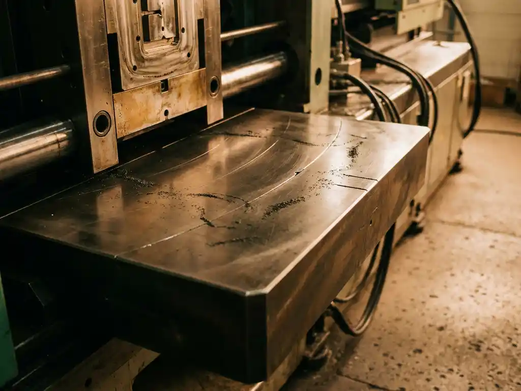
Uneven magnetic field distribution across a clamping surface is caused by a combination of factors including platen geometry, magnet array design, mold back plate material and condition, and the size relationship between the mold and the platen. When any of these variables fall outside optimal parameters, the magnetic force is no longer evenly distributed, which can lead to mold movement, flash, or even a dropped mold. The sections below walk through each contributing factor and what you can do about it.
What factors cause magnetic field strength to vary across a platen?
Magnetic field strength varies across a platen primarily because of how the magnet array is arranged, the quality of the platen steel, and any physical gaps or discontinuities between the magnet surface and the mold. Even a well-designed magnetic clamping system will show some natural variation at the edges of the pole pattern, where flux lines diverge rather than flow straight through the contact surface.
Several factors compound this baseline variation in practice:
- Magnet array layout: Pole pitch and polarity alternation determine where flux concentrates. Gaps between poles are inherently lower-flux zones.
- Platen steel grade: Inconsistent permeability in the platen material causes flux to travel unevenly through it.
- Surface flatness: Any deviation from a flat platen surface creates an air gap, and even a fraction of a millimeter of air gap dramatically reduces local holding force.
- Thermal gradients: Heat from the injection molding process can temporarily reduce magnet output, and if the platen heats unevenly, field distribution shifts accordingly.
Understanding these root causes helps you identify which variable is most likely responsible when clamping performance degrades over time.
How does mold back plate condition affect magnetic clamping performance?
The mold back plate is the interface through which magnetic flux travels from the platen into the mold. If the back plate is made of the wrong material, is too thin, is corroded, or has surface damage, it disrupts the magnetic circuit and reduces holding force, often unevenly across the contact area.
For a magnetic clamping system to perform reliably, the back plate must be made from a magnetically soft ferritic steel with high relative permeability. Stainless steel back plates, for example, are often non-magnetic or only weakly magnetic, which severely limits flux transfer. Even with the correct material, the following conditions degrade performance:
- Surface rust or scale: Creates a non-conductive layer that increases the effective air gap locally.
- Machining marks or weld seams: Irregular surface texture prevents full contact across the platen face.
- Insufficient back plate thickness: A plate that is too thin saturates magnetically and cannot carry the full flux load, causing force to drop off at the center or edges depending on the pole layout.
- Warping from thermal cycling: Repeated heating and cooling can bow the back plate slightly, introducing a variable air gap across the surface.
Inspecting and maintaining mold back plates is one of the most cost-effective ways to protect consistent magnetic clamping performance across a production run. To learn more about how our systems are engineered around these challenges, visit our magnetic clamping products page.
What is the difference between permanent magnet and electromagnet field distribution?
Permanent magnet systems produce a fixed, always-on field whose distribution is determined entirely by the physical arrangement of the magnet array. Electromagnet systems allow field strength to be varied by adjusting current, which gives operators some ability to tune force output, but the spatial distribution of the field is still governed by coil geometry and core design.
In practice, this distinction has real implications for field uniformity:
- Permanent magnet systems (including permanent-electromagnetic hybrids that use a brief electrical pulse to switch state) have a very stable field that does not drift with temperature or power fluctuations once set. However, their distribution pattern is fixed and cannot be adjusted to compensate for an unusual mold geometry.
- Electromagnet systems can be tuned in real time and can, in principle, apply different force levels to different zones of the platen if the coil layout supports it. This makes them more adaptable but also more sensitive to power supply stability and coil condition.
For most injection molding applications, permanent magnet technology offers more consistent field distribution over time because there are fewer variables that can shift during a production run.
Why does mold size relative to platen size cause clamping issues?
When a mold is significantly smaller than the platen, only a portion of the magnet array is covered by the mold back plate. The uncovered magnets still generate flux, but that flux has nowhere useful to go, which can cause it to redirect in ways that reduce force under the mold or create stray fields that interfere with nearby equipment.
Conversely, when a mold is close to or larger than the active magnet zone, the flux path becomes crowded at the edges and field uniformity suffers at the perimeter of the contact area. The ideal scenario is a mold back plate that covers the magnet array fully and symmetrically, allowing each pole pair to complete its circuit cleanly through the mold.
Practical rules to follow when matching mold to platen:
- Aim for the mold back plate to cover at least the central active magnet zone of the platen.
- Avoid positioning a small mold at one corner or edge of a large platen, as this creates a highly asymmetric flux path.
- When running multiple small molds on a single platen, check that the combined footprint still engages enough pole pairs to meet the required clamping force.
How can uneven field distribution be detected before it causes a problem?
Uneven magnetic field distribution can be detected using a Gaussmeter or Hall effect probe to map field strength at multiple points across the platen surface. By scanning the surface in a grid pattern before clamping a mold, you can identify zones where flux density is lower than expected and investigate the cause before a mold shift or production defect occurs.
Beyond direct field measurement, several indirect indicators suggest that field distribution may be uneven:
- Flash appearing consistently on one side of the part: Suggests the mold is not held with equal force across its face, allowing one parting line edge to open slightly under injection pressure.
- Clamping force readings that do not match expected values: Most modern magnetic clamping systems include force monitoring; a reading below the calculated minimum for a given mold and platen combination warrants investigation.
- Visible wear patterns on the back plate: Polished spots or uneven contact marks after a mold has been run indicate that only part of the surface was in firm magnetic contact.
- Repeated mold micro-movement during cycling: Even small shifts visible on precision sensors point to insufficient or uneven holding force.
Routine platen and back plate inspections, combined with force verification at changeover, catch most field distribution problems before they escalate. Exploring the full range of magnetic clamping applications can also help you benchmark your setup against proven industry configurations.
What adjustments or system choices reduce field non-uniformity in practice?
Reducing field non-uniformity comes down to optimizing the magnetic circuit at every point: the platen, the magnet array design, the mold back plate, and the mechanical contact between them. No single adjustment eliminates all variation, but addressing each factor systematically brings field distribution within acceptable limits for reliable clamping.
Key adjustments and design choices that make a measurable difference:
- Specify back plate material correctly: Use low-carbon ferritic steel with documented permeability, and set a minimum thickness standard based on the flux load required.
- Maintain platen and back plate flatness: Periodic surface grinding of worn platens and replacement of warped back plates restores the contact quality the magnetic circuit depends on.
- Choose a magnet array designed for your mold range: Arrays with finer pole pitch distribute force more evenly across smaller molds. Discuss your mold size range with your supplier before specifying a system.
- Use zone-based force monitoring: Systems that measure clamping force independently in multiple platen zones can flag asymmetric conditions automatically.
- Control platen temperature: Where process heat is a concern, thermal management of the platen protects both magnet output and field uniformity.
How EAS Change Systems Helps with Magnetic Clamping
We at EAS Change Systems have been developing and supplying magnetic clamping solutions since 1985, and the field distribution challenges described above are exactly what our engineering team designs against. Our Pressmag LP and SP magnetic clamping systems are built around permanent-electromagnetic technology, which combines the stability of a permanent magnet field with the convenience of electrically controlled engagement and release. This approach delivers consistent field distribution without the ongoing energy consumption or power dependency of a purely electromagnetic design.
Here is what we bring to projects where magnetic field uniformity is a priority:
- Application engineering: We assess your mold range, back plate specifications, and platen dimensions before recommending a system, so the magnet array is matched to your actual production requirements.
- Back plate guidance: We provide material and thickness specifications for mold back plates to ensure the magnetic circuit performs as designed.
- Force monitoring integration: Our systems can be paired with clamping force verification to give operators real-time confidence that the mold is held correctly before injection begins.
- OEM and retrofit options: Whether you are specifying a new machine or upgrading an existing press, our Pressmag systems are designed for integration into both scenarios.
- Service and maintenance support: We offer ongoing support to keep platens and systems performing to specification over the long term.
If you are experiencing inconsistent clamping results or want to evaluate whether magnetic clamping is right for your application, contact EAS Change Systems to speak with one of our application engineers. We will help you identify the right system and back plate configuration for your specific mold and press combination.