

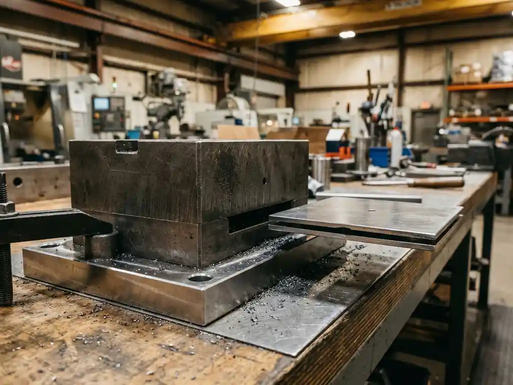
Part thickness has a direct and significant impact on holding force in magnetic clamping systems. As the thickness of a ferromagnetic part decreases, the magnetic flux that can pass through it becomes limited, reducing the effective holding force at the clamping surface. Understanding this relationship is essential for anyone designing or operating a magnetic clamping setup, and the sections below address the most common questions engineers face when working with thinner parts.
What happens to holding force as part thickness decreases?
As part thickness decreases, holding force in a magnetic clamping system drops, often sharply below a critical threshold. Magnetic flux requires sufficient ferromagnetic material to travel through the part and complete the circuit back to the magnet. When the part is too thin to carry the full flux, magnetic saturation occurs in the material, and the excess flux disperses rather than contributing to clamping force.
In practical terms, this means a part that is half the optimal thickness does not simply deliver half the holding force. The relationship is nonlinear. Once the material begins to saturate, each further reduction in thickness causes a progressively steeper drop in clamping performance. For production environments where setup reliability is non-negotiable, this is a critical factor to account for during tooling design and process planning.
The effect is most pronounced with permanent magnet and electropermanent magnet systems, where the magnetic circuit is fixed. With electromagnets, adjusting current can sometimes partially compensate, but the fundamental physics of flux saturation still applies.
What is the minimum part thickness for reliable magnetic clamping?
The minimum part thickness for reliable magnetic clamping depends on the magnet type and its pole pitch, but as a general principle, the part should be thick enough to avoid magnetic saturation. For most industrial magnetic clamping systems, a minimum thickness of around 20 to 25 millimeters of ferromagnetic material is commonly cited as a practical starting point, though the exact value varies by system design and pole geometry.
Pole pitch, which is the distance between adjacent north and south poles on the magnet face, is the key reference dimension. A widely accepted guideline is that the part thickness should be at least equal to half the pole pitch to allow the flux to travel through the material without saturating. Below this threshold, holding force becomes unpredictable and potentially unsafe for production use.
It is always advisable to consult the magnet manufacturer’s specifications and, where possible, perform pull-off force tests with representative parts before committing to a magnetic clamping solution for thin workpieces.
How does material type interact with thickness to affect clamping force?
Material type and part thickness interact directly because different ferromagnetic materials have different magnetic permeability and saturation points. A part made from low-carbon steel, which has high permeability, can carry more flux at a given thickness than a part made from a material with lower permeability, such as certain tool steels or cast irons. This means the effective minimum thickness varies depending on what the part is made of.
Hardened steels, for example, often have lower magnetic permeability than soft steels. A hardened mold plate of the same physical thickness as a soft steel plate may reach magnetic saturation sooner, resulting in lower holding force. Similarly, cast iron, while ferromagnetic, has permeability characteristics that differ from wrought steel, and its graphite content can interrupt flux paths at a microstructural level.
Non-ferromagnetic materials such as aluminum, stainless steel grades with an austenitic structure, or certain titanium alloys are not magnetically attracted at all, making magnetic clamping unsuitable regardless of thickness. When a mold or die plate includes non-ferromagnetic inserts or backing plates, the effective magnetic thickness may be less than the physical thickness suggests. Exploring the full range of magnetic clamping applications can help clarify which material and thickness combinations are viable for your production environment.
Why does air gap matter as much as thickness in magnetic clamping?
Air gap matters as much as thickness in magnetic clamping because magnetic force drops off exponentially with distance. Even a small air gap between the magnet face and the part surface, caused by surface contamination, poor flatness, or surface texture, can reduce holding force dramatically. In some cases, a gap of just a fraction of a millimeter can cut effective clamping force by a significant margin.
This is why surface preparation and flatness tolerances are treated as seriously as material selection in magnetic clamping applications. A part that meets the minimum thickness requirement but has a rough or uneven contact surface may still underperform because the effective air gap increases the magnetic reluctance of the circuit, limiting flux transfer.
In mold clamping applications, mold plates with parting line flash, corrosion, or machining marks on the clamping face introduce unintended air gaps. Regular inspection and maintenance of both the magnet face and the mold contact surface are essential practices for sustaining consistent holding force over time. Thickness and surface condition should always be evaluated together, not in isolation.
How can you compensate for thin parts in a magnetic clamping setup?
When parts are thinner than the recommended minimum for a magnetic clamping system, several practical strategies can help compensate and restore reliable holding force. The right approach depends on the specific application, the degree of thickness shortfall, and the flexibility available in the tooling or machine setup.
- Use a ferromagnetic backing plate: Attaching a sufficiently thick steel plate to the back of a thin mold or die plate increases the total magnetic thickness, allowing the flux to complete its circuit without saturating. The backing plate effectively becomes part of the magnetic circuit.
- Select a magnet with a smaller pole pitch: A magnet designed with a finer pole pitch requires less material thickness to achieve saturation-free flux transfer. Matching the pole pitch to the available part thickness is a fundamental design consideration.
- Switch to a higher-force magnet system: Using a more powerful magnet can partially offset the reduced efficiency caused by thin material, though this does not eliminate the saturation problem and has practical limits.
- Evaluate mechanical clamping as a supplement: In cases where magnetic clamping alone cannot deliver sufficient force for a thin part, combining magnetic clamping with mechanical clamps provides a safety margin without abandoning the speed benefits of magnetic technology.
- Redesign the tooling where possible: If production volumes justify it, modifying the mold or die plate to increase the contact thickness in the clamping zone is the most reliable long-term solution.
Each of these approaches involves trade-offs in cost, complexity, or cycle time, so the best solution depends on a thorough assessment of the specific production environment and the forces required.
How EAS Change Systems helps with magnetic clamping for varying part thicknesses
We at EAS Change Systems understand that magnetic clamping performance is not one-size-fits-all, especially when part thickness varies across a production line. Our Pressmag LP and SP magnetic clamping systems are engineered with these real-world challenges in mind, offering solutions that account for material type, thickness, and surface condition to deliver consistent, reliable holding force.
Here is what we bring to the table:
- Application engineering support: We assess your specific mold or die dimensions, material grades, and production requirements to recommend the right magnetic clamping configuration from the start.
- Pressmag LP and SP systems: Our permanent and electropermanent magnetic clamping solutions are designed to optimize flux transfer across a range of part thicknesses, with pole geometries matched to common tooling standards.
- Adaptive clamping systems: For mixed production environments where mold or die thickness varies between runs, our adaptive clamping solutions help maintain safe and efficient changeovers without compromising holding force.
- ROI and force calculations: We provide detailed holding force calculations and ROI analysis so you can make informed decisions before committing to a system.
- Installation, service, and maintenance: Our team supports you through installation and ongoing maintenance to ensure your magnetic clamping system continues to perform as intended over time.
If you are working with thin mold plates or need guidance on whether magnetic clamping is right for your application, contact EAS Change Systems today to speak with one of our application engineers and get a solution tailored to your production needs.