

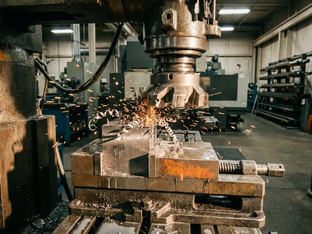
Heavy-duty milling operations generally require clamping forces ranging from 10 kN to well over 100 kN, depending on workpiece size, cutting tool diameter, feed rate, and material hardness. The higher the material resistance and the more aggressive the cutting parameters, the greater the force needed to keep the workpiece securely in place. The sections below break down how that force is calculated, what drives it up, and how to verify that your setup is adequate.
How is clamping force calculated for milling operations?
Clamping force for milling is calculated by estimating the cutting force generated during the operation and then applying a safety factor to ensure the workpiece cannot shift or lift. A common starting point is to calculate the tangential cutting force based on material-specific cutting pressure, depth of cut, feed per tooth, and the number of cutting edges engaged. The required clamping force must exceed this cutting force by a defined safety margin, typically between 1.5 and 3 times the estimated cutting load.
The basic formula most engineers use looks at specific cutting force (measured in N/mm²), chip cross-section area, and the number of active cutting edges. From there, the result is divided by the coefficient of friction between the workpiece and the fixture surface to determine the minimum clamping force required. A smooth steel surface on a smooth steel fixture, for example, has a low friction coefficient, meaning more clamping force is needed to achieve the same holding effect compared to a surface with higher friction or a textured contact area.
Practical calculation tools, fixture design software, and machine tool manufacturer guidelines all support this process. However, the calculated value should always be treated as a minimum baseline. Real-world conditions introduce vibration, thermal expansion, and tool runout that can push forces beyond theoretical predictions.
What factors increase clamping force requirements in heavy-duty milling?
Several factors drive up the clamping force needed in heavy-duty milling. The most significant are material hardness, depth of cut, feed rate, and tool diameter. Hard materials like hardened steel, titanium, and nickel alloys generate substantially higher cutting resistance than aluminum or soft steel, which directly increases the force trying to displace the workpiece.
- Depth of cut: Deeper cuts engage more material per pass, multiplying the cutting force and therefore the required holding force.
- Feed rate and spindle speed: Higher feed rates increase chip load, which amplifies the lateral and vertical forces acting on the part.
- Tool diameter and number of flutes: Larger diameter tools and more cutting edges simultaneously in contact generate greater cumulative cutting forces.
- Workpiece geometry: Thin-walled or asymmetric parts are more susceptible to deflection and vibration, requiring additional clamping support to compensate.
- Interrupted cuts: Milling across slots, holes, or uneven surfaces creates impact loads that are harder to predict and require a higher safety margin.
- Coolant and vibration: Coolant can reduce friction between the workpiece and fixture, while vibration from aggressive cutting reduces effective clamping grip.
In heavy-duty operations, any one of these factors alone can push clamping requirements significantly higher. When multiple factors combine, the cumulative effect can be dramatic, making it essential to account for worst-case conditions rather than average cutting loads.
What happens when clamping force is insufficient during milling?
When clamping force is insufficient during milling, the workpiece can shift, vibrate, or lift off the fixture surface. Even minor movement of just a fraction of a millimeter is enough to cause dimensional errors, surface finish defects, and scrapped parts. In severe cases, the workpiece can be ejected from the fixture entirely, creating a serious safety hazard for operators and equipment.
Beyond the immediate risk of part movement, inadequate clamping accelerates tool wear. When the workpiece is not held rigidly, the cutting tool experiences uneven loading and chatter, which shortens tool life and increases the frequency of tool changes. This adds cost and downtime that compounds quickly in high-volume production environments.
Chatter, the rhythmic vibration caused by insufficient rigidity in the workpiece-fixture-machine system, is one of the clearest signs that clamping is not adequate. It produces a characteristic surface pattern on the machined part and an audible resonance during cutting. Addressing chatter by reducing cutting parameters treats the symptom but not the root cause. Increasing clamping force or improving fixture design is the correct response.
How does clamping method affect the force needed?
The clamping method directly influences how much force is required because different methods distribute load differently and provide varying levels of rigidity. Mechanical clamps, hydraulic clamps, and magnetic clamping systems each have distinct characteristics that affect both the force they can generate and how effectively that force is transmitted to the workpiece. Exploring the full range of clamping products available can help identify the most suitable method for a given operation.
Mechanical and hydraulic clamping
Mechanical clamps are simple and reliable but apply force at discrete contact points, which can create localized stress and uneven holding if the workpiece geometry is complex. Hydraulic clamps offer consistent, controllable force and can be integrated into fixtures for faster changeovers. They are well suited to high-force applications and can be designed to apply force from multiple directions simultaneously, improving overall rigidity.
Magnetic clamping systems
Magnetic clamping distributes holding force evenly across the entire contact surface of the workpiece rather than at isolated points. This uniform distribution reduces the risk of workpiece deformation and allows for better surface contact, which in practice means that the total clamping force required can sometimes be lower than with point-contact mechanical methods while still achieving equivalent or superior rigidity. Magnetic clamping systems are particularly effective for flat or plate-like workpieces and are widely used in industrial milling and tooling applications where fast setup changes are a priority. Their holding force is typically rated in force per unit area, making it straightforward to match the system to the workpiece size and cutting load.
The choice of clamping method also affects setup time and repeatability. A method that delivers consistent, repeatable clamping force reduces variability between setups, which is especially important in high-precision or high-volume milling operations.
When should clamping force be verified or re-evaluated?
Clamping force should be verified whenever cutting parameters change, a new material is introduced, or a new fixture is put into service. It should also be re-evaluated after any incident involving workpiece movement, chatter, or unexpected tool wear, as these are reliable indicators that the current clamping setup may no longer be adequate.
Routine re-evaluation is also warranted in the following situations:
- When tooling is upgraded to larger diameters or higher feed-rate capability
- When the workpiece design changes shape, weight, or material grade
- When fixture components show signs of wear, particularly clamping surfaces and sealing elements in hydraulic systems
- When production speeds are increased to improve throughput
- When a new machine tool with different spindle power or rigidity characteristics is introduced
Verification does not always require complex measurement equipment. A structured review of cutting parameters against the original clamping force calculation, combined with a physical inspection of the fixture and clamping components, is often sufficient to confirm that the setup remains appropriate. For critical applications or high-value workpieces, dynamic force measurement during test cuts provides a more precise confirmation.
How EAS Change Systems helps with clamping in milling and tooling applications
We at EAS Change Systems design and supply clamping solutions built for demanding industrial environments, including applications where clamping force, setup speed, and repeatability all matter. Our range is broad enough to address a wide variety of workpiece types and machine configurations:
- Magnetic clamping systems (Pressmag LP and SP): These systems use magnetic technology to fix molds and workpieces securely in machines, distributing holding force evenly across the contact surface for consistent, reliable grip without point-contact stress.
- Hydraulic clamps (MOD, ELY, and HECS): Our hydraulic clamping options deliver controlled, high clamping forces suitable for heavy-duty applications, and are designed for integration into both new and existing equipment.
- Adaptive clamping systems: Engineered to accommodate varying workpiece geometries and production requirements, these systems support fast changeovers without sacrificing holding performance.
Whether you are evaluating a new fixture setup, upgrading an existing line, or working through a clamping challenge on a specific application, we can help you identify the right solution. Contact our team to discuss your requirements and find the clamping configuration that fits your operation.