

Sink marks in injection moulding appear as surface depressions or indentations on finished plastic parts. They occur when material shrinks unevenly during cooling, creating visible defects that affect both appearance and part quality. Proper mould design, process parameter control and injection moulding optimisation techniques can effectively prevent these common manufacturing issues.
What are sink marks in injection moulding and why do they occur?
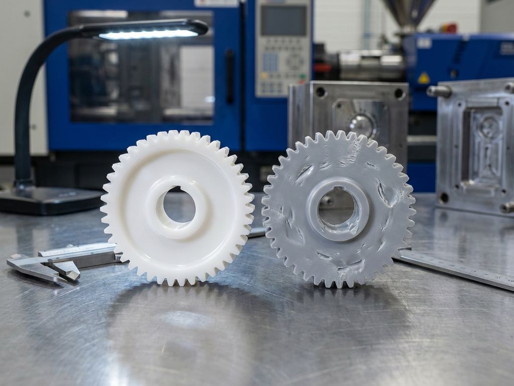
Sink marks are surface depressions or indentations that appear on injection-moulded plastic parts, typically opposite thick sections or ribs. They manifest as visible dimples, waves or uneven surfaces that compromise the aesthetic and functional quality of finished products.
These defects occur due to several interconnected factors during the cooling process. When molten plastic cools and solidifies, it naturally shrinks. However, uneven cooling rates across different part thicknesses create internal stresses and surface deformations. Thick sections take longer to cool than thin walls, causing the material to pull inward as it contracts.
Insufficient packing pressure compounds this problem by failing to compensate for material shrinkage. During the packing phase, additional material should be forced into the mould cavity to fill voids created by cooling shrinkage. When packing pressure is inadequate or applied for an insufficient time, sink marks become inevitable.
Material shrinkage rates vary significantly between different plastic types. Semi-crystalline materials like polypropylene and polyethylene exhibit higher shrinkage rates than amorphous plastics, making them more susceptible to sink mark formation without proper process control.
What are the main causes of sink marks in plastic injection moulding?
Wall thickness variations represent the primary cause of sink marks in injection-moulded parts. When thick sections exist adjacent to thin walls, differential cooling rates create internal stresses that manifest as surface depressions opposite the thick areas.
Gate design significantly influences sink mark formation. Poor gate placement forces material to flow through restrictions or creates weld lines, leading to uneven filling and cooling patterns. Gates positioned too far from thick sections cannot provide adequate packing pressure where it is needed most.
Inadequate cooling time prevents uniform solidification throughout the part thickness. Rushing the cooling phase to reduce cycle times often results in parts that have not fully solidified, causing post-mould shrinkage and sink mark development.
Insufficient injection pressure creates similar problems by failing to completely fill the mould cavity or maintain adequate packing pressure. This leads to material voids and uneven density distribution that appear as surface defects.
Material-related factors include moisture content, melt flow characteristics and shrinkage properties. Hygroscopic materials containing excess moisture can cause bubbling and uneven cooling, while materials with high shrinkage rates require more aggressive packing strategies to prevent sink marks.
How can you prevent sink marks through proper mould design?
Uniform wall thickness is the most effective design strategy for preventing sink marks. Maintaining consistent wall thickness eliminates differential cooling rates that create internal stresses and surface deformations throughout the part.
When design requirements necessitate varying wall thicknesses, gradual transitions between thick and thin sections minimise stress concentrations. Avoid sudden thickness changes that create hot spots and uneven cooling patterns.
Strategic gate placement ensures adequate material flow and packing pressure reach all areas of the part. Position gates near thick sections to provide maximum packing effectiveness where shrinkage is greatest. Multiple gates may be necessary for complex geometries.
Cooling channel optimisation involves designing conformal cooling that follows part contours and maintains consistent temperatures across the mould surface. Proper cooling channel diameter, spacing and flow rates ensure uniform heat extraction.
Rib design considerations include limiting rib thickness to 60–80% of the nominal wall thickness and incorporating draft angles for easy part ejection. Hollow or cored ribs can provide structural strength while minimising material volume and shrinkage potential.
What injection moulding process parameters help reduce sink marks?
Proper injection pressure settings ensure complete cavity filling and adequate material packing. Higher injection pressures overcome flow restrictions and guarantee material reaches all mould areas, particularly thick sections prone to sink mark formation.
Holding pressure adjustments compensate for material shrinkage during cooling. Maintain holding pressure at 50–80% of injection pressure for sufficient time to allow material solidification. The holding time should extend until the gate has completely solidified.
Cooling time optimisation balances cycle efficiency with part quality requirements. Extend cooling time sufficiently to allow uniform solidification throughout the part thickness, particularly for thick sections that retain heat longer.
Melt temperature control affects material flow characteristics and shrinkage behaviour. Higher melt temperatures improve flow and packing ability but may increase shrinkage rates. Find the optimal temperature balance for your specific material and part geometry.
Cycle time modifications should prioritise quality over speed when sink marks occur. Gradually increase cooling time and holding pressure duration while monitoring part quality improvements. Injection moulding optimisation requires systematic parameter adjustments based on part inspection results.
How do EAS change systems help with sink mark reduction?
EAS quick mould change systems enable rapid testing of different mould designs and configurations to optimise sink mark prevention. The ability to swap moulds quickly allows manufacturers to experiment with various gate positions, cooling channel layouts and design modifications without extensive downtime.
Our advanced clamping and coupling solutions provide several benefits for sink mark reduction:
- Rapid mould swapping facilitates testing of different cooling channel configurations
- Consistent clamping pressure ensures uniform mould closure and part quality
- Advanced coupling systems maintain precise temperature control throughout the mould
- Quick changeover capability allows process optimisation without production delays
- Integrated systems support systematic testing of injection moulding optimisation parameters
The precision and repeatability of EAS systems enable manufacturers to quickly identify optimal mould designs and process parameters that eliminate sink marks. This systematic approach to problem-solving reduces development time and improves part quality consistency. For manufacturers across various industrial applications, our solutions provide the flexibility needed to perfect injection moulding processes. Contact EAS today to discover how our quick mould change solutions can enhance your injection moulding optimisation efforts and eliminate sink mark defects in your production process.